- All Categories
- ELECTRONICS
-

-
Z braces for Wanhao Duplicator I3
Z braces for Wanhao Duplicator I3
by AzzA, published Jul 12, 2015
$9.89
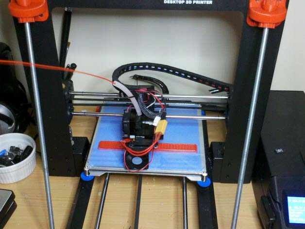
SummaryThis kit will add rigidity to your Di3 giving you better prints more often. My i3 was one of the first batch shipped and it suffered a mild flogging as a result of the first generation of packaging not being of the best design.
Print request
Free .stl file
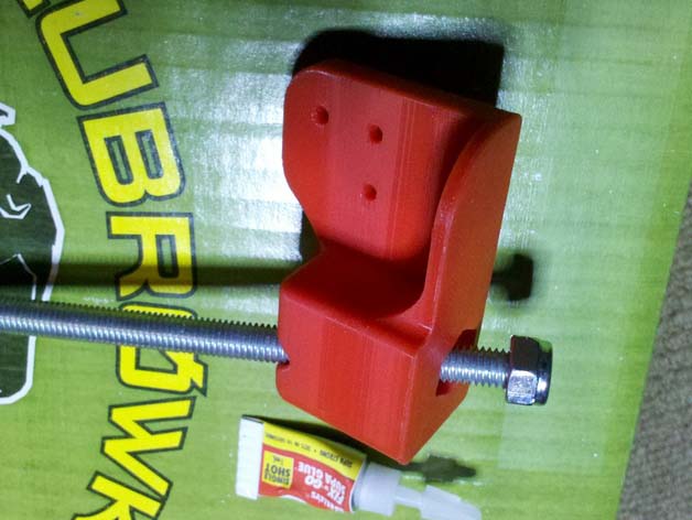
DOWNLOADSummary This kit will add rigidity to your Di3 giving you better prints more often. My i3 was one of the first batch shipped and it suffered a mild flogging as a result of the first generation of packaging not being of the best design. Try as I might, I was not able to adjust the Z axis to be square; there simply was not enough adjustment available from the OEM fasteners . An otherwise great printer was less than perfect. Design time... The design uses 8mm or 5/16" threaded rod that locks at the base and has adjustment at the top. No need to drill any new holes in the i3, but you do need to replace few 3mm screws for longer ones. The original base base design had two nuts each, one being a Nyloc nut. It was too fiddly to get the slop out of the two nut version, so this design is now gone from Thingumyverse.
There are now two choices of front feet/bases:
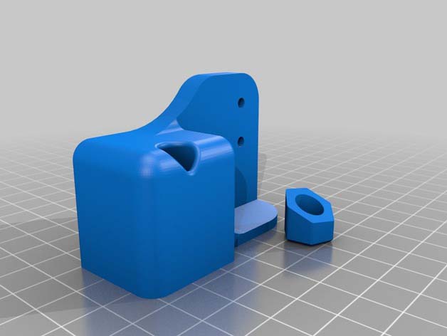
- BottomxxxxxForOneNut Glue is needed for the one Nyloc nut design to glue in the nut plug (use a Nyloc nut facing with nylon end downwards).
- BottomxxxxxForBalls The base/foot design using two nuts, on in ball, is more or less self explanatory.. an upside-down Nyloc nut in the base and a plane nut in a ball.
With the printer now supported at all four corners there is none of the rocking that most owners are reporting. Gluing rubber pads under the feet would complete the design and assists greatly in isolating noise from the printer being amplified by your desktop/table. The design files may be edited with the free 3D design software from RS, DesignSpark Mechanical. You can get it from Radio Spares website "rs-components dot com", just look for the "DesignSpark" link on your local distributors front page. http://www.rs-online.com/designspark/electronics/eng/page/mechanical All files have been inspected in Simplify3D. All files should now be manifold and compliant to your slicer. Tested in Cura & S3D. "BackFootxxxxx.2.2.stl" files are for use with larger rubber pads. Very sturdy. Assembly pictures are being uploaded, slowly. They will specifically be for the bottoms using one Nyloc nut (BottomxxxxxForOneNut.stl). However the assembly method is otherwise the same. I've added a functional "front Y brace" to the Z brace mod. Now V3 (final version). It uses a 4.8mm wide cable tie to tension the belt idler bolt... and hold itself onto the printer. The 3mm by 5mm screws, left over from the Z brace mod will fit the front Y brace. I've added two files for Back Y Braces. One is for most people and one is for people contemplating using a cable chain on the Y-axis (it has the fairly obvious extra bit with all the holes). Cable chain selected is 7mm x 7mm ID which is the same generic chain used elsewhere on the Di3. You can buy it on eBay etc. Like the Front Y-axis brace, this new one also uses the short M3 screws left over from the other mods. I've printed the one for the chain, which is directly based on the other, and it works well. Far more rigidity on the back frame plate now; I have a resilient motor mount fitted and it flexes before anything else does. That is rigid enough. 2015/08/10 03:17 AEST Everything is pretty much done on the design side of things for this project; it's all ready to print and assemble. (There is now 1m more clearance for the loom cable/zip ties on the back brace; it was a tad tight on one of my Di3's... sorry if you are one of the 4~5 early downloaders.) Enjoy. Let us know what you think. Any feedback is welcome, within reason ;-)
Instructions Warning!!! Your printer may be bent or off-square and you do not realise it. Before putting any strain on the rod, release the tension on the four screws that secure the Z-towers to the Y-axis. Failure to do this may result in distortion of your printer! If there is not enough range of movement, to make the Z-Y axis square, remove each of the rear Z-tower to Y-axis screws. (With this mod', one screw is sufficient.) Print the stl's as supplied. 1mm walls, or 3 shells, and about 50% infill @ 0.2mm seems to be enough. PLA or ABS, or your choice. They're rock solid in PLA! Sufficiently over-engineered, shall we say. When printing all parts, there are no supports required. Use brims (5 worked for me) if you're printing the "BottomxxxxxForOneNut.stl" parts; the small "nut plug" does not have a lot of surface area on the print bed. Bases print as they are to stand/mount, and require a little support but only touching the build plate... they probably don't really need that. Back legs flat, no support needed. Choose balls or balls mk2, your choice smooth or grippy. Just print the balls as they appear in the preview, with support disabled, and near enough to full infill. The plug in the middle of the ball is for support, it will pull out cleanly with needle nose pliers, so you do not need to enable support in your slicer.
Parts required:
- 2 x 400-410mm of 8mm or 5/16" threaded rod,
- 2 to 6 x 8mm or 5/16" nuts,
- 2 or 4 x 8mm or 5/16" Nylocs
- (Final number of nuts depend on version used.)
- 20 x M3x10mm (or sufficiently long enough)
- Rubber feet (whatever you've got that fit, self adhesive or glue-on)
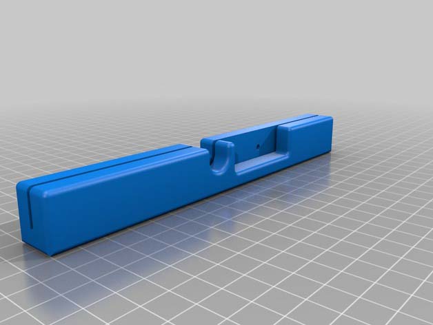
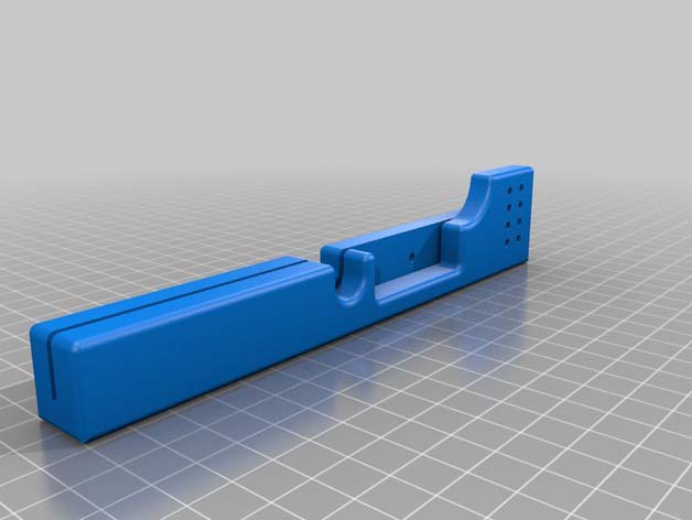
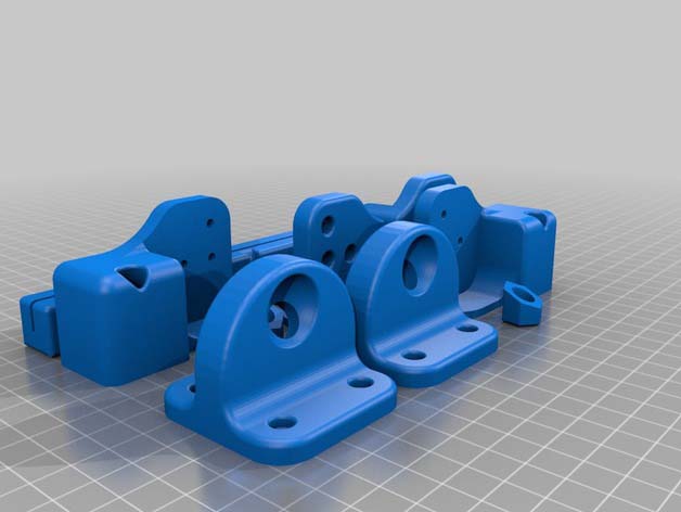
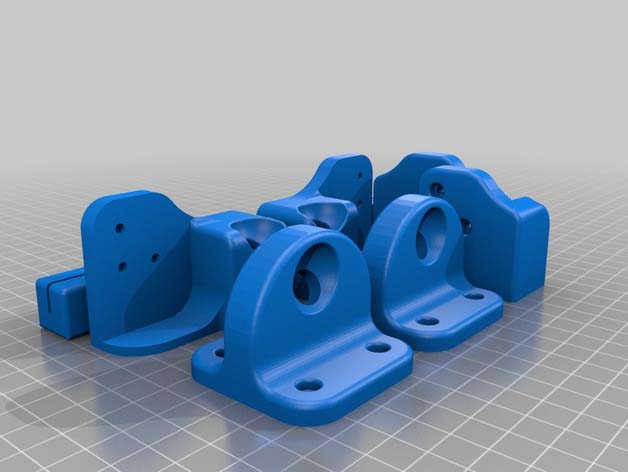
Printed parts:
- all versions-
- ‘TopLeft.stl’
- ‘TopRight.stl’
- 2x Balls.stl or 2x ballsMk2.stl (your choice)
There's two choices of front feet:
- ( 1.) -if using two nuts on each front foot ‘BottomRightForBalls.stl’ ‘BottomLeftForBalls.stl’ (also found on "Plate2.stl") 1x Balls.stl or 1x ballsMk2.stl (your choice)
- ( 2.) for one Nyloc nut and a glued plug on each foot- BottomRightForOneNut.stl BottomLeftForOneNut.stl (also found on "Plate1.stl")
There's two c3hoices of back feet: ( 1.) (also found on "Platex.stl" files) BackFootxxxx.2.2.stl very sturdy and have big bases for bugger rubber pads, and (2.) Foot_Rear_xxxxx.stl which are quicker to print but don't have much bottom are to stick rubber pads onto.
Nuts, how many? As few as 6 nuts, or as many as 8, depending on which front foot design you choose. At least 1 nut on each rod should be a Nyloc. I suggest one Nyloc nut inside each front foot. If you don't have at least one Nyloc then Loctite or glue the bottom most nut into the front foot; because you need something to stop the threaded rod from turning, or ever vibrating loose.
Assembly? Obvious for some but there can be a few hurdles.
If you are having trouble inserting the rod: Move the printer so that the front feet are over the edge of your table/bench. That way the rod can be dropped lower than the level of the table, and easily lifted up through the hole in the top bracket. If you find your rod does not align to both holes, in the foot to the top bracket, your printer is bent! (Mine was too, "hello sailor", welcome to the club.)
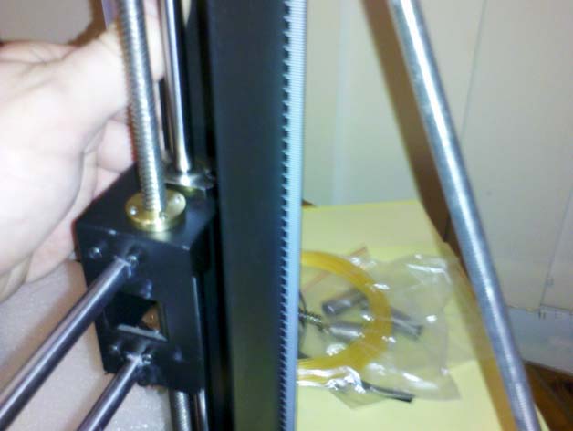
If your printer is bent: There are two large hex-headed machine screws holding each Z-tower in place. Release the tension on both screws until you have enough movement in the Z-axis to insert the rods. If there is not enough movement with both loose screws, then you need to remove one screw from each tower (I removed the rear most screw, but it doesn't matter which just do the same on both towers). YOUR Z TOWER CAN NOW FALL OVER... DO NOT DROP IT!
Squaring your printer: Get yourself a large engineers/carpenters square, any tools store or hardware store should have them or you can steal your fathers (he wont miss it immediately). Place the printer on a smooth flat surface (Mums dining table is usually the best; she had dad pay a fortune for it.) Ensure the bottom of the rods are fixed tight into the front feet. Adjust the nuts using the balls on the top brackets to square the printer to the tabletop/bench-top. it might be difficult to find a straight edge on the printer Z-tower to use your square against; I used the front edge closest to the outermost corner, or bend. (If you're using mums furniture, be careful not to scratch it unless you have younger/weaker siblings.) Once everything is square, tighten the balls. Then recheck for square. Repeat until satisfied. Your printer should now be able to travel back to its normal place of rest without coming out of square. (Scatter some of your smaller siblings toys to cover any "tracks" you might have left.)
Checking: Now home the axis and level the print-bed. Print something with long square edges in the Y and Z planes, and check the finished print against your square (your new one or dads old one, if he hasn't missed it yet).
Printing details not available.